SystemC based ESL methodologies
  SystemC - IP | SERVICES | TRAINING                                                                
  • Home
  • Company
    • About Us
    • Alliances
    • Testimonials
    • Awards & Recognition
  • Offerings
    • SystemC Modeling - Services >
      • Virtual Prototype - Development, Deployment & Verification
      • Architecture & Performance modeling
      • High Level Synthesis
    • SystemC Modeling - IP
    • Corporate Training
  • News & Events
    • Events
    • blog
    • News
    • Technical Articles
  • Career
    • Life at CircuitSutra
    • Why Circuitsutra
    • Opportunities
    • Apply Now
  • Contact US
    • Contact Information
    • Enquiry Form

SystemC Methodology for Virtual Prototype

7/16/2020

2 Comments


SystemC, a C++ library, offers the nuts and bolts to model the hardware at various abstraction levels.
Developing each IP model from scratch with low level semantics and boilerplate code can be a drain on engineering time and resources, leading to lower productivity and higher chances of introducing bugs. There is a need for a boost-like utility library on top of SystemC, that provides a rich collection of tool independent, re-usable modeling components that can be used across many IPs and SoCs.
​
One of the strengths of SystemC, and also its biggest weakness, is its versatility. SystemC allows you to develop models which can be at the RTL level, similar to Verilog / VHDL. It also allows you to develop the models at higher abstraction levels which can simulate as fast as real hardware. To effectively deploy SystemC in your projects, just learning the SystemC language is not sufficient, you need to understand the specific modeling techniques so that models are suitable for a specific use case. The modeling methodology or boost-like library on top of SystemC, for virtual prototyping use case should provide the re-usable modeling classes & components that encapsulate the modeling techniques required in virtual prototyping. Any model developed using this library will automatically be at higher abstraction levels, fully suitable for virtual prototypes.

Most of the semiconductor companies working on virtual platform projects end up developing such a library in-house in a tool independent fashion.

Over the years the team at CircuitSutra has built up their own SystemC library to accelerate virtual prototype projects. CircuitSutra Modeling Library (CSTML) has been successfully used in a wide variety of virtual platform projects for over a decade, and has become highly stable over that period of time.
Using CSTML as the base for your projects right from the beginning will ensure that your models are compliant with standards and can be integrated with any EDA tool. You may also use it as the base and further customize it to define your own modeling methodology.

READ MORE ..

2 Comments

Migrating open source software algorithms to semiconductor chips using high-level synthesis

5/7/2020

2 Comments

 
The focus area of this blog is how to migrate the open source software algorithms to Verilog and accelerate these inside the semiconductor chips.

Many semiconductor companies are designing custom SoCs for emerging domains like Vision, Speech, Video / Image processing, 5G, Deep learning etc.. In these domains lots of algorithms are already available as a software implementation, either as a free open source version, or the companies have their own software implementation.
In general, the software world has a huge code base available as free and open source code, most of which is widely used by the industry and is thoroughly verified. Many popular algorithms are available as an open source implementation, along with comprehensive reference test suites.
​
If we can come up with a robust methodology where an existing software implementation can be quickly implemented into silicon, it can be a big game changer for the industry

READ MORE ..

2 Comments

Development of Arm based systems with Synopsys Virtual Prototyping: Anytime, Anywhere

5/5/2020

1 Comment

 
An article by Kamal Desai, Product Marketing Manager at Synopsys

Virtual prototypes are fast, fully functional software models of complete systems that execute unmodified production code and provide unparalleled debug efficiency
READ MORE ..
1 Comment

circuitsutra technologies - redefining the simulation modeling methodologies

10/20/2018

2 Comments

 
Modeling methodologies are going to play an important role in the emerging trends in the semiconductor
industry. A specialized SoC for deep learning and artificial intelligence is one such emerging trend. Risc-V, an open
source instruction set architecture is enabling a new era of processor innovation. CircuitSutra is in the process of fine-tuning its modeling methodologies for these areas.
Read More ..
2 Comments

The DNA of an Artificial Intelligence SoC

8/15/2018

48 Comments

 
An article by Ron Lowman, Synopsys

Neural networks are what we define as deep learning, which is a subset of machine learning, which is yet a subset of AI. This is an important classification because it isn’t AI or more specifically machine learning that is changing the system-on-ship (SoC) architecture designs but it is the subset known as deep learning that is.  

​Read More ..

48 Comments

11 Myths About High-Level-Synthesis Techniques for Programming FPGAs

7/1/2018

1 Comment

 
An article by Tom Hill, Intel published in ElectronicDesign  

An HDL is used to implement a register-transfer-level (RTL) abstraction of a design. In time, the process of creating RTL abstractions was made easier through the use of reusable IP blocks, speeding the design-flow process. As designs became more complex and the time-to-market pressures increased, developers and the vendor community have strived to provide more software-based tool chains to help reduce development times.
One of these techniques is “high level synthesis” (HLS). HLS can be thought of as a productivity tool for hardware designs. It typically uses C/C++ source files to generate RTL that is, in most cases, optimized for a particular target ..

Read More ..


1 Comment

SystemC Ecosystem gets boost with Accellera’s new SystemC CCI 1.0 Standard

6/15/2018

0 Comments

 
New standard enables greater interoperability among tools and models

More ..
0 Comments

Shifting Left—Building Systems & Software before Hardware Lands

5/18/2018

0 Comments

 
This article By Michael G. (Intel), talks about the usage of Virtual Prototypes at Intel for achieving 'Shift Left'.

Read More ..
0 Comments

Computer Vision and High-Level Synthesis

5/1/2018

0 Comments

 
An article by Daniel Payne, Semiwiki.com
 
Interesting article exploring the suitability of High-Level Synthesis for the semiconductor chips for vision processing ..
Read More ..

0 Comments

Virtual Prototype- It’s more than a pre-hardware tool

1/30/2018

12 Comments

 
by Niharika Singh | SMTS, CircuitSutra                                                                                             Jan 30, 2018
The use of virtual prototyping prior to the availability of physical hardware has been well-documented. The most common use cases involve architectural exploration, early software development, golden reference specifications, reduced silicon turns, software/hardware co-verification etc.

A common misconception is that once the physical hardware is available all software development should switch to hardware and no longer use the Virtual Prototype (VP). This article focuses on the VP benefits after physical hardware is available. It highlights various efficient and economical use cases of VP which are valid even when suitable physical hardware is available due to its benefits of visibility, controllability, availability, repeatability and testability.

Debug Capability:

During firmware development/validation software developers often need to step and debug the running firmware image. Debugging on physical hardware is expensive, limited to processor boundary and is relatively slow when compared to VP.
Picture
As debugging on VP is same as debugging another set of software one can synchronously pause and restart the processor core and targeted firmware image on it. Multi-core debugging further accentuates the need for virtual prototypes as the parallel cores can be stopped in synchronization and can be viewed at the same time. Gathering of debugging data on the physical hardware typically only occurs if there is a specific need, while gathering of debugging data in a VP environment can occur for every event or on every simulation run. Additionally during debugging product flash memory may need to re-program again and again, which is often a time consuming process on physical hardware but a quick approach on VP.  This useful VP debug environment does not go away once the physical hardware is available. In fact it becomes more useful and provides another way to work through issues that are found on the physical hardware.
Picture
System Visibility:                                                     
​VPs provide many levels of visibility to the user. The extensive simulation visibility of VP helps significantly to measure/control the internal working of processor core. When working on VP one can record internal signal changes, or even internal memory modifications in a file (in the form of VCD, binary or any other supported format). These files then can be viewed in various programs provided by EDA tool vendors such as GtkWave and SimVision etc.
​
On the hardware it is often difficult, if not impossible to measure the time from interrupt request assertion to the beginning of the actual software interrupt service routine. But on VP it is just about calculating the simulation time difference between the two events. One can also trace and view the internal state of processor core when working on VP but on physical hardware only the processor boundary can be accessed. 
Picture
Advance Control Capability:                            
​The controllability of the VP is superior to the physical hardware because of the direct tie between the processor core and other peripherals. On VP read of a processor register or port may causes the firmware to act as if the fault had occurred and enable full validation of the various diagnostic routines. The careful control of simulation stimuli on VP can expose faulty implementation and significantly reduce the efforts/time taken to validate the various complex system level requirements. For instance validating various fault injection scenarios on physical hardware would normally require custom hardware variants but on VP it can be reproduced with just a register read/write.
Picture
Portability:                                                           
As running firmware/application software on VP is just running another piece of software, it offers greater design portability than physical hardware. VP availability enables worldwide development teams to quickly begin creating target firmware rather than trying to replicate, or share a similar physical bench system.
During software development/validation engineers often need to share their design across different teams, location etc. When working on physical bench environment, achieving design repeatability requires elaborate tool interconnections to power on/off the system, program various connected devices, monitor analog outputs, and provide run-time control of the hardware unit. But VP offers built-in repeatability and therefore allows the simulation to react in the same manner on each run without any additional external connection. 
Picture
Availability:                                                    
The virtual-ness of the virtual prototype allows for greater availability of the development environment for engineers working in a global and even local environment.

A typical physical bench embedded software development requires a hardware board, power supplies, oscilloscopes, voltage and current meters, connections for debuggers, and additional setup to provide stimuli. Therefore the hardware bench setup is often very costly and may escalate project cost. In the early development stages of a project access to the hardware development bench is often very limited which in turn limits the amount of development that a software engineer can accomplish on the actual hardware.
​
In contrast, VPs make the entire test bench just another piece of software. This allows worldwide development teams to quickly begin creating target firmware rather than trying to replicate, or share, a physical bench system. It involves little cost of tool licensing, in replicating and deploying a virtual test bench to software developers in any global location once the initial development is completed. Additionally availability of VP even after the hardware test panel has been produced, enables higher productivity and a better use of engineering resources.
Picture
Architecture Exploration:                                              
VP also enables early architecture exploration for next generation of chips. Scaling physical hardware to adapt the new specifications, features is not possible. Developing RTL implementation requires huge effort and development process is relatively longer. Therefore when full functional models are not required, system architects often prefer VP to test new features and validate the hardware capabilities. VP provides fast platform setup, easy exploration of new scenarios and hence supports system architects in their decision making process.
 
Therefore, availability of the VP is essential even when the physical hardware is available due to the reduced costs of replication, ability to distribute designs, and the flexibility to change or add new features.
12 Comments

Survey Report on Model Driven Engineering in Semiconductor Domain

12/6/2017

2 Comments

 
2 Comments

​Power of Virtual Prototype

10/5/2017

2 Comments

 
With increasing complexity, chip design is associated with longer development and verification phases. Since time to market is a major factor to win the business, high-quality tests for post-silicon validation should be ready before a silicon device becomes available to conserve time after the device is ready. However, to ensure the verification quality we also need to be sure of the post-silicon tests ‘quality and readiness.

Test coverage plays a critical role in determining the quality and readiness of tests. Coverage results provide valuable input to judge whether tests are good enough to achieve the expected quality on the device or not. However quantifying coverage of post-silicon validation tests is very challenging due to the black box nature of silicon device which limits controllability and observability. It also consumes a lion’s share of overall product development time and cost due to the black box nature of silicon device and dependency on Silicon to develop, evaluate and debug the tests.
One alternative solution for early bring up of post-silicon tests is using RTL simulation or emulation. However, this is practically difficult to realize due to the slow simulation speed, expensive emulation tools cost, integration complexity of RTL design and lack of complete availability of RTL design. Even if the tests are prepared, debugging and fixing the tests takes considerable time due to the low-level abstraction and limited controllability.

An attractive alternative for this is the usage of Virtual prototype (also popularly termed as VP). VP is extensively used in development of software device drivers, application software, and fault injection validation during pre-silicon stage. Virtual prototypes provide the same transaction level functionalities as silicon devices. Transaction level implementation makes it many times faster as compared to RTL emulation or RTL simulation. It also provides higher degree of observability, traceability and controllability. As simulation speed and white box nature of the design are critical factors in development of post silicon validation tests, VP can play a very important role.  Therefore VP is the best alternative to estimate the silicon device functional coverage as compared to RTL simulation or emulation and hence validating the readiness of the test suite.

In this article, we discuss various coverage metrics essential for checking the readiness of post silicon tests. We also cover virtual prototype implementation and the limitations of this approach.

PREREQUISITE

It is important to select an appropriate coverage metrics for Virtual Prototype to quantify the completeness of test suite. Coverage results observed by running test suite on virtual prototype needs to reflect the coverage on silicon device as virtual prototype models the same characteristics of the silicon device. Therefore adopting a right combination of conventional coverage metrics along with model specific coverage metric is essential. Typical coverage metrics include structural (code) coverage metrics like functional coverage, decision coverage, statement coverage, block coverage. Model specific coverage can be register coverage, internal states coverage, etc.

i. Function Coverage: It provides precise information about evaluating device features described in specification. Quantification Accuracy of Functional Coverage depends on virtual model implementation. Clear judgement can be made out of the results, if each feature in the specification is mapped to a function in virtual model.
​
ii. Statement Coverage: This is a simple and fundamental metric for test coverage. This makes sure that every statement in the model code is executed at least once.

iii. Decision Coverage: Decision Coverage, aka branch coverage, is another key metric because it covers multiple execution paths through the code. It obviously requires more test scenarios to achieve various outcomes but provides a more in-depth view of the source code than simple statement coverage.

iv. Register Coverage: To ensure completeness of the tests, test scenarios need to access all the registers in the module. Register Coverage is very critical in ensuring all the registers and its bit fields are implemented as per specification. Virtual model provides complete visibility and traceability support for registers.
Picture
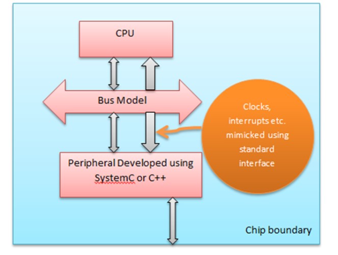
Figure 1 Typical Implementation of VP

​IMPLEMENTATION
Figure above shows a typical VP implementation, it consists of core model, bus model and peripheral models developed using high level languages like C, C++, SystemC etc. These models are integrated in Virtual Platforms Tools like Synopsys Virtualizer, CoMET or ASTCs VLab to create complete Virtual Prototype of Silicon device. So, the same executable (elf/hex/target) code which runs on real silicon can be run on VP as well. Based on the VP environment, a suitable Coverage tool should be selected (there are many free and licensed tool available like OpenCppCoverage, CTC++ and Squish-Coco etc.).

To determine quality and reediness of post silicon tests one should run the tests on VP with coverage enabled (this process might be different for different coverage tools). It will give an estimate of the functions/register (as all registers in VP are modelled in terms of get set function) or branch coverage captured by a given test thus will help to improve the quality of test.

LIMITATIONS 
Though Virtual Prototypes provide the same transaction level functionalities as Silicon device, Virtual models may not be as timing accurate as Silicon, so the test designed to validate timing behaviour of IP models might not give the desired output on VP. Therefore Coverage estimation on virtual devices may not always accurately reflect the functional Silicon device Coverage.

We hope this article helps you to get a glimpse of VP’s importance in Post-Silicon validation.  Feel free to provide your feedback / opinion in the comment section below. 
2 Comments

Portable Stimulus Status Report

9/12/2017

1 Comment

 
Portable Stimulus could be the first new language and abstraction for verification in two decades.
Brian Bailey
Read More ...

1 Comment

CircuitSutra: Blending ESL with Current Methodologies

5/1/2017

1 Comment

 
Advanced tools and methodologies have become absolutely essential to achieve the necessary productivity, quality, cost and performance expected in a design process because of the complexities of the current systems. One of the important tenets in ESL Design is the necessity of early design analysis.
Read More ..
1 Comment

SSD & NAND controller software development using Virtual Prototypes

4/28/2017

4 Comments

 
An interesting article about how Virtual Prototypes provides tremendous benefits in the embedded software development for SSD & NAND controller.
Read More ..
4 Comments

Propelling embedded software market forward by modeling platforms of tomorrow TODAY

1/14/2017

0 Comments

 
Virtual Prototyping plays an important role in embedded technology as it helps to dry-run and test the product before committing to a particular design. This article by CIO Review magazine, talks about the modeling offerings of CircuitSutra 

Read more ..

0 Comments

Performance analysis, an important step in SoC design

1/4/2017

0 Comments

 
Achieving the optimum performance and power consumption are important factors in designing the complex SoCs of today. This interesting article by Colin Osborne & Peter Hawkins from ARM, provides an overview of the techniques to be used for performance analysis of ARM based SoC.

Read more ..

0 Comments

A practical approach to building a Virtual Prototype

12/21/2016

1 Comment

 
​This article by Bernard Murphy, is a summary of white paper released by Synopsys, detailing a practical approach to building a Virtual Prototype of an SoC. Juno ARM development platform is used as the illustration to explain the approach.

Read more ..

1 Comment

Enabling Effective and Reliable ESL Methodologies to Design Complex SoC

10/29/2016

0 Comments

 
ESL methodologies are a set of advanced methodologies for the design and verification of complete systems that encompass the System, SoC, IP & Software. These methodologies help the customers to reduce the time to market for their products, and to design the products which are better optimized for power, performance & area.

An article by Silicon Review magazine about CircuitSutra 

Read more ..
0 Comments

Verification of SystemC models and Virtual Prototypes

10/16/2016

1 Comment

 
A major factor which determines the Success/Failure of current products/systems is Time to Market.  As the time to market is becoming more critical than ever day after day , the early software development is becoming one of the most important component in today’s SOC / product development.  Effectively Developing, Integrating and Validating firmware/software within the stipulated timeline is becoming so important that software teams now cannot wait till availability of silicon on development boards.  Thus it is now absolute necessity to make available, accurate, fast and low cost Virtual Hardware Platforms, to software teams very early in the product development cycle
SystemC TLM2.0 based models are currently the best available/ widely used technology to create Virtual Platforms in today’s world.  These models additionally are useful in architectural Exploration and also can act as golden standard Reference model for RTL / Netlist  verification.
As the industry has now widely starting using the SystemC models in various stages of the SOC/ASIC product development cycle, their verification has also come out to an additional challenge.   At CircuitSutra, we have long been involved in the development and verification of SystemC / TLM models .  In this article we will discuss about various techniques that are most effective for SystemC / TLM model verification and their respective use cases.

The 3 most effective approaches for Model verification are -
  1. Directed unit testing approach
  2. Using the already available RTL testbench to verify  IP models.
  3. Using System Universal Verification Methodology(UVM)  to verify complex SoC / IP Models.
We will discuss each individually next in detail-

VERIFICATION USING DIRECTED TESTS      
Directed testing is a straightforward approach to functional verification. For writing directed tests we pick a feature, write a test to verify that feature and repeat the process until all the features are tested. However with increasing design size and complexity the number of directed tests required for verification are increasing exponentially.

Two kind of verification setup are feasible to enable the directed testing.

One simple setup is to develop the testbench for a specific IP model. This testbench should allow to read / write the value of registers of the IP, read / write the value of pins of the IP. CircuitSutra modeling methodology provides a python based unit testing framework.

The other setup is to get the virtual prototype of the complete SoC by connecting the IP models with the processor models as per the address map of SoC. The testcase is written in the form of bare metal embedded code, that is cross compiled and executed on the virtual prototype. This bare metal code, configures the IP for a certain functionality by writing to the registers of the IP, and checks the correctness of specific functionality by checking the value of related register & memory addresses etc..
At Circuitsutra we follow a hybrid approach for doing functional verification with directed tests. We have divided the verification process into three phases:-

i) Establish a baseline for directed testing:-
The goal of the first phase is to establish a solid baseline to support subsequent testing/verification. In this phase all possible testable features of IP Models are identified using the specification document and a list of generic test cases are developed for sanity testing of IP Models in order to ensure stability of test framework and that of IP Models code base. Directed tests in this phase don’t require implementation of a coverage model or a completed design or verification environment, so results in this phase are quick and easy to quantify.

ii)  Developing direct test case:
This phase is a transition phase that builds on top of the directed tests and test/verification environment developed in phase i. In this phase test developed in phase 1 are modified and tested with random test data of various kinds in order build a strong productive environment for verification of IP models.

To support random inputs:-
At Circuitsutra we use an open source tool DGL in order to generate test data of various kinds. DGL is a data generation language developed by University of Florida that can be used to generate test data systematically, randomly, or a combination of both. The goal of DGL usage is to reduce the complexity of test cases, number of test cases by capturing multiple combinations under one test and capture more functional coverage. In order to use and generate test inputs using DGL we write test cases to test a set of input configuration and then generate multiple different combinations of that input configurations using DGL productions.

For analog and communication IP:-
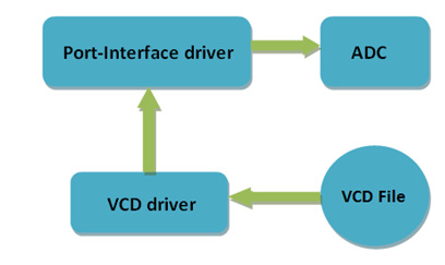
To test analog IP such as ADC , A continuous analog input signal is required and for this at Circuitsutra we use generic systemC IP(port interface driver) to drive input port of analog module IP by using python VCD driver. To drive input port at particular time for defined duration VCD driver uses .vcd file ( contain port name, input value & time duration etc), VCD driver written in python read vcd file parameters and call wrapper API’s of port interface driver to drive input ports of analog devices .

Picture
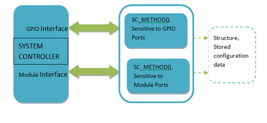
To test communication module such as I2C, SPI, CAN etc , we have generic SystemC test bench which has two interfaces such as GPIO interface and Module interface. Test bench GPIO ports have connection with system GPIO ports to transfer module specific configuration data and store all received data in a structure. Once test bench receive data by module interface it start comparing received data with stored configuration and shows comparison result.
Picture
iii) Exhaustive Testing with random inputs and coverage measurement:-
Phase 3 starts when all basic and critical features of the IP Model have been verified rigorously and as a result, the design can reasonably be expected to handle the full scope of legal stimulus.
The goal in phase 3 is to exercise difficult corner conditions as efficiently as possible. Tests written in this phase are lightly constrained and focus more towards the code coverage of IP models. Additionally in this stage, a second class of directed tests is written as needed for focusing on error conditions and/or hard-to-reach corner scenarios of the IP model functionality.

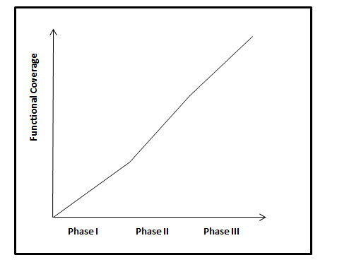
Following figure represent the functional coverage progress during each phase.

Picture
Advantages and disadvantages of using this approach has been summarised below -
Advantages-

  1. It is easier and quicker way for IP verification.
  2. Helps to find the redundant lines of code in IP model.
  3. With little modification tests written via this approach can be reused for successive versions of IP models.
  4. Possible to simulate hardware behaviour for analog devices.
  5. Able to verify communication IP with virtual slave device.
Disadvantages -
  1. This approach require availability of an integrated platform and toolset for compiling C/C++ based test cases, loading it, running and debugging it on the virtual platform.
  2. Manual writing of each test case takes more time as compared to automated constrained random testing.
  3. Additional tool support is required for external stimulus, debugging etc.

VERIFICATION USING RTL TESTBENCH / VERIFICATION ENVIRONMENT
Lots of advancement have happened in the the RTL verification methodologies over past decades. A very comprehensive verification of the RTL is done before the design goes for the tape out. The same verification setup, if used for the verification of SystemC models will ensure that SystemC models are of the equally high quality as the hardware.
This methodology is useful when the SystemC models are developed for the IP whose RTL is already available. For any new SoC design it is becoming mandatory to develop the virtual prototype, most of these new SoC designs reuses the existing well tested IPs. The SystemC models of these existing IPs may be verified using the existing RTL verification setup of these IPs.
For the new IPs also it makes sense to verify the SystemC models using the RTL verification environment, once the RTL design & verification is complete. In the initial phases the virtual prototype can be verified using directed tests, later when the RTL verification environment becomes available, the virtual prototype can be further verified using the RTL verification setup. Primary motivation for virtual prototype development is to enable pre-silicon embedded software development, however going forward more and more companies are using virtual prototypes for post silicon use cases as well. Semiconductor companies are required to provide the virtual prototype of their SoC to their customers, who utilize these for their system level verification and firmware development. For such post silicon use cases of the virtual prototype, expectation is that quality of the virtual prototype should be as good as real hardware.

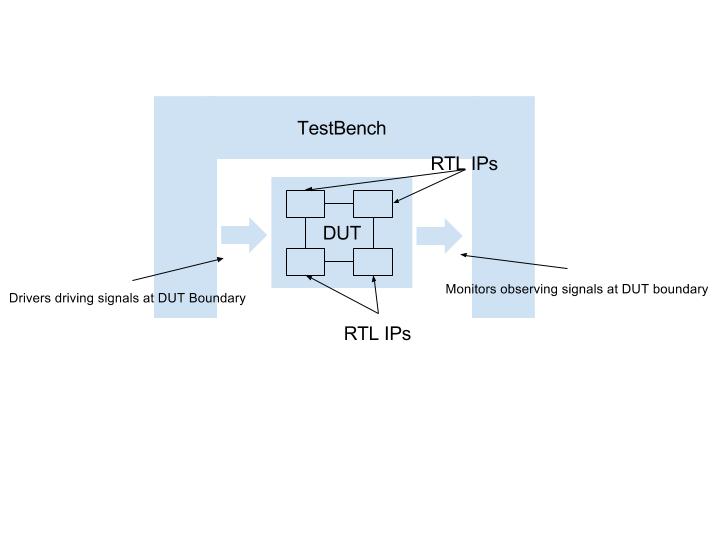
In our use case, a RTL Verification environment can be shown as in the diagram below. All the RTL IPs in DUT were connected together and  stimulus was applied at the DUT Boundary and signals were also observed at the DUT boundary . 
Picture
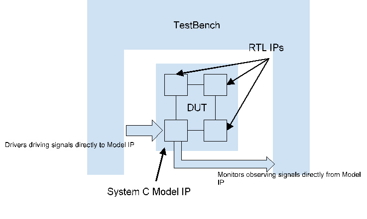
​To use the RTL testbench to verify the SystemC Model, the RTL IP was replaced by the Model IP in the DUT.  
Picture
In the diagram above it is shown that the TB was directly connected to the ports/pins at model boundary and all the RTL IPs were bypassed. The connection was  done by mapping the HDL paths of the Model IP with the corresponding signals in Testbench.  

It requires to develop the specialized transactors, drivers / monitors etc.. to connect the pin level cycle accurate world to the transaction level, loosely timed models. This kind of setup requires co-simulation of SystemC / C models along with RTL. Similar setup can also be created using hybrid co-emulation methodologies.

RTL verification technology has evolved to be very advanced and state of art.  A typical Hardware verification language such as System Verilog, Specman E etc already have features builtin to achieve the most effective verification.  Some of these features are -
  1. Exhaustive list of supported data types including dynamic arrays, associative arrays, queues, structs, unions , real, int etc for verification. As well as data types like bit, byte, vectored arrays,  nets and regs for description of hardware.
  2. They supports full Object Oriented Programming which make it very easy to manage large code base of tests and environment.
  3. Have built in constraint specification which helps in generating useful random data for stimulus as according to constraints in design.
  4. Inbuilt full functional coverage modelling language without which it becomes almost impossible to measure the achievement  verification of goals with random stimuli.
  5. Ability to fork of parallel threads of verification sequences and interprocess synchronisation using mutex and semaphores.
  6.  Rich assertion language which makes specifying temporal property/conditions checks very easy.

Pros and Cons of this approach has been summarised below -
Advantages-
  1. RTL tests are already available, this saves a lot of test development effort.
  2. Minor to medium changes in the TB environment needed.
  3. Replacing RTL ip instances with SystemC ip models with some stitching code enough to start with
  4. Give jumpstart to model verification
  5.  RTL simulators/Debug tools are already at state of art level , which helps a lot in quick effective debugging
  6. HVL like System Verilog etc.  have inbuilt advanced features like Constraint Randomisation, Functional Coverage capturing,  Assertions,  OOPs which help with very effective and complete verification.
  7. As the everything is already in use for RTL verification, reuse saves lot of effort/money
  8. RTL verification engineers can perform Model verification without much knowledge of systemC.

Disadvantages -
  1. This technique is only most useful if RTL verification is already done / is in advanced stage.  If model has to be verified early better to use SystemC for Verification.
  2. As RTL has tests have requirement for cycle/timing accuracy,  all tests are not valid.  Some tests are overkill and require workaround/debug in environment, which is not relevant to model verification.
  3. Most useful for IP level test. System level tests are a big challenge.

VERIFICATION USING SYSTEMC UVM

As electronic systems are getting complex day by day  so are their virtual prototypes or simulation models. SystemC helps creating models in short time as it has constructs required to model hardware easily along with lot more other features and uses abstract communication (TLM). But as models are getting complex  verifying them also is taking considerable amount of time & effort. Till now as there is no standard methodology for system level verification, companies are following their own flows and testbench creation methods, where testbenches and stimulus needs to be created for each module and also again at system level.

UVM (Universal Verification Methodology) is a standard verification methodology which specifies how to construct a test environment which is modular, scalable, configurable and reusable. UVM (or its predecessors like OVM) implementation in SystemVerilog is kind of defacto for block level/RTL verification. 

Even though SystemC is the standard system level design language till now it was lacking support of a unified verification methodology. UVM-SystemC standard promises to decrease the system level verification effort by implementing UVM methodology in SystemC. With this standard there is lot of possibility for reusing test infra from module level to system level. And also it helps in achieving better test coverage. Testbench components may be reused from system level to block level also. Tests and testbenches can also be reused across verification and validation.

As SystemC-AMS helps in modeling heterogeneous systems  there is also some effort going on in extending UVM for SystemC-AMS also. This will help in verifying full system model (digital + mixed-signal) with a single testbench.

Summary

As Discussed above all the 3 techniques used have their unique use case.  

Directed tests are very useful to verify IPs/System when models have been integrated into Virtual Platform.  It allows verification engineer to verify models keeping the perspective of the firmware engineer.  As the tests are run on the on-chip processor, the tests are very near to real life use cases.  But verifying individual IPs is tedious with this approach.

On the other hand, using RTL Testbench is most effective in verification of IPs standalone. It can cover vast stimulus using constrained random and generating unthinkable scenarios to catch tough bugs. It is very cost effective as Test Bench is already available and verification can be quickly kickstarted.  But It is very complex to verify whole system or integrated Virtual platform.

UVM SystemC is alternatively very efficient with both IP and System level verification. It is very structured methodology, created using most effective time tested methods for verification.  It makes code reuse very easy.  As it is standard, Maintenance is very easy.  But It is very complex to build a verification environment, takes much extra development time when done from scratch. But once developed, modification is easy.

As we can see, All the said techniques are very effective in their respective use case. No technique is best and has its pros and cons. The best use of any technique can only be made by determining various factors like schedule , complexity of design, availability of resources, cost , Verification goals et cetera.  At CircuitSutra we have been pioneering Model verification since many years and with dozen of projects successfully completed.  We can help companies determine and deploy the most effective or all technique for complete verification of their SystemC Model/Virtual Platform.
1 Comment

SystemC Power modeling with TSMC System-PPA

10/10/2016

0 Comments

 
This is an interesting article about how the SystemC TLM models can be instrumented with the power analysis data extracted from the real chip designs using the System-PPA, a new ESL power modeling methodology developed by TSMC.

These models can be integrated with the architecture analysis and simulation platforms like Synopsys Platform Architect.
​
Read more ..
0 Comments

Importance of Architecture modeling for Power analysis

7/5/2016

1 Comment

 
Electronics System Level (ESL) methodologies enables the SoC companies and electronics companies to optimize their products for power, performance & area. This article by ANN STEFFORA MUTSCHLER, talks about the importance of System level power modeling & analysis.

​Read more ..


1 Comment

Using QEMU in SystemC based Virtual Platform

1/4/2016

0 Comments

 
Qemu is an open-source processor emulator and can be freely downloaded from www.qemu.org. It is a fast open-source processor emulator and its performance is very close to Host machine performance as it does dynamic translation of Guest instructions into Host machine instructions and run them on Host thus decreasing the boot-time & run-time of the applications running on the simulated platform. Qemu is completely implemented in ‘C’ language and have its own simulation engine. It supports various CPU architectures; ARM, Micro blaze, PowerPC, Sparc to a name a few and also allows us to enhance or add new CPU architecture. It also supports various IP models and reference boards using which one can readily bring-up a SoC and run either bare-metal application or full-fledged OS.
As we are aware, SystemC is a standard language for the modelling of SoC & Electronics system. It is becoming a language of choice for SoC companies and Electronics system companies to develop virtual prototypes of their SoC & Electronic system. SystemC being a standard, allows the interoperability of models from various third parties, and can simulate in the popular virtual prototyping tools.

Being discussed about the two simulators, one would obviously try to leverage the mature Qemu CPU models and reference boards in their SystemC Virtual Prototypes. But there are certain road blocks to do this. Qemu is entirely implemented in ‘C’ language and uses its own simulation engine. It does not inter operate with SystemC simulation engine, ports, interfaces, signals, events etc., Hence QEMU does not fit with the SystemC based design and verification flows. Lots of models and reference boards can be readily used without having to develop everything from scratch if we enable Qemu’s integration with SystemC.

In this article we discuss about how we can enable this integration.

Extend Qemu with SystemC – CST_QEMU 

The solution is to extend Qemu with SystemC.  We have developed CST_QEMU by developing a SystemC / TLM2.0 wrapper over QEMU. CST_QEMU implements the following features.

  • Synchronising Qemu and SystemC simulation engines.We have implemented two different mechanisms for synchronization, one is to synchronize after every N number of instructions, and the other is to synchronize after certain time quantum. In both cases, user can configure the frequency of synchronization, depending on the speed and timing accuracy requirement.
 
systemc_timer = timer_new_ns(QEMU_CLOCK_VIRTUAL, sc_timer_cb, _model_wrapper);
timer_mod(systemc_timer, qemu_clock_get_ns(QEMU_CLOCK_VIRTUAL));

static void sc_timer_cb(void *opaque)
{
  int64_t qemu_time_vm = qemu_clock_get_ns(QEMU_CLOCK_VIRTUAL);
  int64_t next_systemc_qemu_time;
 
  next_systemc_qemu_time = time_based_qemu_cpu_sync_sc(opaque, qemu_time_vm);
  timer_mod(systemc_timer, next_systemc_qemu_time);
  classPtr->m_quantum_keeper.sync();
}

  • Bus interface exposed through TLM2.0 initiator socket to connect the external SystemC IP models
 
 /**< Master socket. */
    tlm_utils::simple_initiator_socket<cst_cpu_base, 64> t_master_socket;
 
 /**< Access Functions. */
    // performs a TLM write transaction
    virtual int CPU_write_access(uint64_t, uint8_t *, uint32_t);
 
    // performs a TLM read transaction
    virtual int CPU_read_access(uint64_t, uint8_t *, uint32_t);
 
    // perform a direct memory access.
    virtual uint8_t * CPU_direct_memory_access(uint64_t, uint32_t , uint32_t *);

  • Interconnection between SystemC signals and Qemu signals   sc_in<bool> IRQ[64];

void IRQ_update();
void RAISE_IRQ(int irq_num);
void LOWER_IRQ(int irq_num); 

  • Configurable address spaceUser can specify what all address space will be accessed from within QEMU, and what will go out to the SystemC world. This functionality allows users to use the existing reference board from QEMU, and connect the external SystemC models at vacant address space.

  void register_memory_map();
      ops->read  = dmi_cpu_read;
      ops->write = dmi_cpu_write;

            else
            {
                        ops->read  = non_dmi_cpu_read;
                        ops->write = non_dmi_cpu_write;
            }
            ops->endianness = info.endianness;
            ops->impl.min_access_size  = 0;
            ops->impl.max_access_size  = 0;
            ops->valid.min_access_size = 0;
            ops->valid.max_access_size = 0;
            ops->valid.accepts         = NULL;
 
            //NOTE: Cry.Memory leaking here.FIX IT.
            OPAQUE_st *param = (OPAQUE_st*)malloc(sizeof(OPAQUE_st));
            param->prnt           = model_wrapper;
            param->start_address  = info.start_address;
 
            memory_region_init_io(ram, NULL, ops, (void*)param, info.rgn_name, info.size);
            memory_region_add_subregion(sysmem, info.start_address, ram)

  • Flashing the binary, when SystemC IP is used as ROM/flash.
 
    //HACK to write into TLM memory
    uint8_t *ram_ptr = NULL;
    uint32_t ram_size = 0;
    if(qemu_sc_direct_memory_rw != NULL)
        ram_ptr = qemu_sc_direct_memory_rw(model_wrapper,addr,rom->datasize,&ram_size);
    else
        printf("ERROR:qemu_sc_direct_memory_rw is NULL\n");
 
    //printf("DEBUG: ram_ptr=0x%x,addr=0x%x,romsize=0x%x, datasize=0x%x, ram_sz=0x%x\n",
            //ram_ptr,addr, rom->romsize, rom->datasize, ram_size);
 
    if(ram_ptr != NULL) {
        memcpy(ram_ptr, rom->data, rom->datasize);
    } else {
 
​​
Picture
CST_BOARD_ZYNQ
 
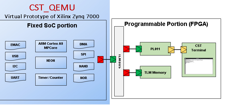
In QEMU there is a reference board for Xilinx Zynq 7000. This virtual platform is implemented by Xilinx and is capable to boot Linux. It represents the virtual model of fixed SoC portion of Zynq 7000. This reference board is extended by CircuitSutra using CST_QEMU, this allows to integrate the SystemC models of additional IP.

This gives us extendable virtual platform of Xilinx Zynq 7000. This virtual platform has two portions. The fixed SoC portion is represented by the model inside QEMU. The design IP that needs to go into the FPGA portion can be modelled using SystemC / TLM2.0 and connected at the vacant address space. Such a setup provides a very powerful development environment to the users of Xilinx Zynq 7000. They can use this virtual platform for the device driver / firmware development for the additional design IP that goes in FPGA portion, or for the embedded application development for the entire system.  It also enables the powerful automated unit testing of firmware / embedded SW.

Results
Using the above methodology, reference virtual platforms were developed mixing the CPU models and IP models from QEMU with the IP models in SystemC.

Summary
CST_QEMU enables one to use rich QEMU infrastructure in SystemC based virtual prototypes   The above discussed methodology can be used for embedded SW development, IP development & testing, automated unit testing of firmware, etc., This methodology is successfully deployed by several customers in their production environment.
References
  1. www.qemu.org
  2. http://accellera.org/
0 Comments

Shift Left: New paradigm in SoC design

11/30/2015

1 Comment

 
SystemC based Virtual Prototypes of SoC & Electronics systems enables the early software development in parallel to hardware design. This is the most popular example of shift-left concept in SoC desigm.

This article by Brian Bailey, covers an interesting discussion about the various methodologies that enable Shift Left paradigm in the SoC design flow. 

Read more ..
1 Comment

VirtualATE: SystemC support for Automatic Test Equipment

11/14/2015

0 Comments

 
This article is the summary of DVCon India 2015 poster session, jointly presented by Continental Automotive & CircuitSutra Technologies.

​In today’s world, ICs are becoming increasingly complex. As a result, the density of ICs is increasing to accommodate more functionality on a smaller area. Competition to release electronic products early in market along with maintaining low costs is increasing among vendors. To achieve this, verification of these ICs in least possible time is the key factor.
 
Especially for analog parts of an IC, a complete parametric test needs to be done after silicon availability. These tests are performed on an automatic test equipment (ATE) controlled by a suite of test-cases. Development of such a testsuite is a time consuming process and debugging possibilities on the ATE system are very limited as long as silicon samples are not available. To create a full suite of correct and running test-cases for an ATE before the targeted IC is actually ready, we simulate the entire test environment using SystemC. In this poster, we focus on challenges and benefits of using SystemC for Virtual prototyping, development and verification of test cases for physical ICs.
 
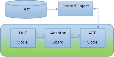
VirtualATE, designed in SystemC, is a model of the programmers interface of the physical ATE system, which includes the drivers and monitors controlled by the test-cases. These drivers and monitors are connected to a SystemC model of the IC. This combined system is compiled into an executable which is static for all tests to be executed. The test-cases are compiled into a shared object that is loaded at run time by the VirtualATE.
 
VirtualATE supplies the inputs to the IC model and collects the outputs. The result file is generated in the same format as on the real ATE system. The generation of this result file includes comparison against a golden reference file to decide whether the test-case is a fail or a pass. However, the VirtualATE system has the advantage that it can be configured to also generate signal traces not only from the pads of the IC but even for internal signals. For the development and debugging of the testcases this is a big advantage even after silicon availability. In this way, a working test-suite can be achieved long before the physical IC is available. These testcases can be directly run on physical IC for its verification once IC is available.
 
Without VirtualATE, we have to wait until the physical IC is released for running the test cases to detect any bugs in the test programs which consumes more time as compared to doing with VirtualATE.
 
Even after silicon availability VirtualATE can still play an important role. One aspect is the before mentioned traceability. On the real ATE system only the pads could be traced via an oscilloscope which can be a time consuming task. The VirtualATE on the other hand allows simple correlation of various (even internal) signals. On real ATE it is difficult to debug some aspects without internal register visibility.

Another aspect that makes the VirtualATE a useful vehicle after silicon availability is the possibility to easily run several instances at the same time. Testsuite development with real ATE is very time consuming as one can not work in parallel unless one acquires several very expensive ATE systems.
 
Test Setup:
The diagram below shows the set-up used for VirtualATE:

Picture
​

​Example:
The below code snippet is from a test program testing an ADC parameter.
 
SetVoltage(AN0, 0.1V)
Wait(Conversion_Time);
adc_result=Raddr(0x0010);
 
In the above code snippet, VirtualATE is setting the voltage of the ADC channel AN0 to 0.1V. After waiting for the conversion time, the digital value from the corresponding result register is read.
 
In this way, inputs can be applied on pins and registers can be read/written to verify the functionality of the models and test programs. Without VirtualATE, we have to wait until the physical IC is released for running the test cases to detect any bugs in the test programs.

Typical test case issues dectected with Virtual ATE
  • Wrong address used in SPI transfer
  • Wrong range expected for result
  • Result stored in wrong location
  • Saturation of ADC not handled correctly
  • Endless loops due to not changing condition
  • Mixing voltages and currents
  • Missing initialization
  • Wrong ADC range
 
Pros:
  1. Time to market of the product reduces as the test program development starts in parallel with physical IC development.
  2. Easy to develop and debug test programs as internal signals and registers can be traced in vcd and log file.
  3. Multiple Instance of VirtualATE can be created so that many people can work in parallel to develop and verify the test programs.
  4. Reusability.
 
Cons:
  1. Models have to be accurate because bugs could increase development time of accurate test programs.
  2. Additional resources are required to develop and maintain the models.
 
Conclusion:
With the VirtualATE setup we are able to develop complete test suites for the ATE system before silicon availability. This approach saves us a development time of 3 to 6 month. Besides these time savings, VirtualATE also allows a more efficient debugging of the test-cases by parallelizing work and the possibility to trace all relevant signals of the DUT.
0 Comments
<<Previous

    Archives

    July 2020
    May 2020
    October 2018
    August 2018
    July 2018
    June 2018
    May 2018
    January 2018
    December 2017
    October 2017
    September 2017
    May 2017
    April 2017
    January 2017
    December 2016
    October 2016
    July 2016
    January 2016
    November 2015
    October 2015
    September 2015
    July 2015
    May 2015
    October 2014
    September 2014

    Categories

    All
    Dvcon
    Dvcon-india
    Esl
    Systemc
    Virtual Platform
    Virtual Prototype

    RSS Feed


© Circuitsutra Technologies Pvt Ltd. Copyright 2014